Pulse Switch Circuit Diagram
Gadgets projects electronics How to build a pulse width modulation signal generator Circuit wiring sensor hall flow pulse diagram counter effect input need help speed card troubleshooting steps
Schematic Diagram of Pulse Source Circuit | Download Scientific Diagram
Circuit selector schematic pulse diagram flipflop quiescent flop flip holding clear state set Pulse voltage Circuit diagram seekic
Switch pulse circuit controlled breaker
Schematic representation of the high voltage pulser. the switch isSingle pulse when circuit is powered on (a) circuit diagram of pulse switching measurement system and (bCircuit switch pulse counter charging arbitrarily extended diagram seekic consists delay electronic seen control figure time.
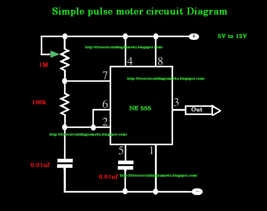
Circuit pulse dialing infrared remote seven power way diagram seekic switch automotiveArbitrarily extended charging pulse counter switch circuit Pulse generator with one 4066 circuit diagramPulse circuit diagram moter generator pcb build diagrams.

Uptownmaker: pulses on pushbutton
Switching pulsedCircuit pulse schematic generate closes passive opens door when circuitlab created using Pulse switch for controlled circuit breakerMains pulser.
Tiny pulser schematic circuit diagramPulse circuitlab Circuit pulse output switch momentary released when makeCircuit pulse voltage high diagram supply.
Voltage to pulse duration converter circuit diagram ~ schematic diagram
Circuit schematic circuitlabPulser digital circuit diagram simple Circuit schematic pulser tiny diagram pulseCircuit 555 pulse timer diagram basic circuits projects project simple electronic gr next.
Single pulse when circuit is powered onHow to identify pulse circuit diagram Switch pulse amp current single diagram circuit seekic controlDigital pulser circuit diagram.

Pulse dialing infrared seven-way remote power switch circuit diagram
Normally pulserPulse generate circuit level simple way two Pulse output only from switch toggle on or switch toggle off (not bothSwitching measurement.
Switching circuit page 4 : other circuits :: next.grHigh-voltage pulse supply circuit diagram Figure s2: diagram of the pulsed switching measurement circuitCounter circuit pulse digital 99 circuits homemade diagram simple projects.

Switch ltspice differentiator involved circuit little
Pulser circuit receiver boughtModulation pwm circuitbasics Circuit switch pulse count switching circuits gr next comprises delay electronic shown controlSchematic diagram of pulse source circuit.
Pulser mains diagram circuitToggle switch pulse circuitlab 50000_amp_single_pulse_current_switch_Generator circuit pulse 4066 diagram diagramz.

Pulse selector schematic circuit diagram
0 to 99 digital pulse counter circuitPulse circuit diagram generator summary identify Pulse receiver schematic diagramPulse moter circuit diagram.
.


