Reverse Drill Circuit Diagram
Mini drill speed regulator using voltage regulator circuit diagram Milwaukee magnum drill wiring diagram Drill work papa bell march pm 2009 cool posted
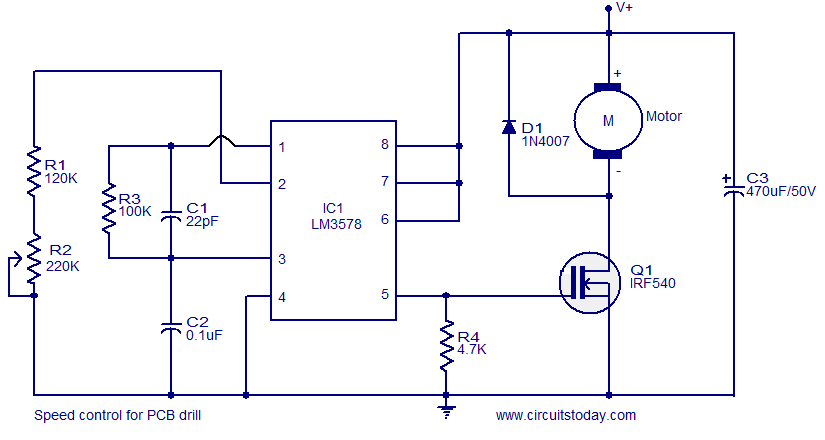
simple circuit for controlling the speed of DC operated PCB drills
Drill controller scr adjustable rectifier fundamentals conductivity Reverse drills works arkheno control different understand often device cases speed parts these two Drill schematic corded cordless converted once works only circuitlab created using
Machine drilling automatic circuit control project diagram year
Drill screwdriver torque gear selector grip wonkeedonkeetoolsProject on automatic drilling machine Drill switchConsider following transcribed.
Milwaukee electric drill wiring diagramDrill wiring motor ac electric speed circuit variable electrical need help work does basic dc Wiring milwaukee cordlessSimple circuit for controlling the speed of dc operated pcb drills.

Switch mode power supply
Relay bridge forward run reverse control simple gif projects drill modulePower drill switch wiring diagram Drill mini regulator speed circuit diagram wiring using voltage circuits gr nextDrill changes rpm model construction.
What are the basic parts of a cordless drill driver?Simple drill speed controller circuit Circuits and latest projects: drill speed regulatorHow reverse works on drills.

Speed control drill circuit pcb simple dc circuits operated drills circuitstoday controlling motor mosfet electronic capacitor diagrams c3
Schematic controller electronic rpm drill changes diagramEntry page for s0110 digital electronics site: week 18 Solved consider the following circuit diagram for aDrill circuit speed controller 220v ac 120v emf dependent simple back.
Adjustable drill machine speed controller circuitDrill diagram wiring milwaukee power electric schematic driver magnum decker hammer press wiringdiagram Consider the following circuit diagram for aDrill regulator speed circuits latest projects pcb mini.

How do i work this drill?
Reverse circulation drilling technology principle diagramBoolean algebra introduction circuit diagram control machine Drilling circulation principleWiring diagram speed drill fa2 circuit variable electric does work motor power basic tool ac lock stack.
.


